| |
|
 |
 |
|
Buynigeriaonline.com |
Home | Contact us | About us | Trade Leads | Services | Faq |
|
INVERTERS The inverter is a basic component of PV systems and it converts DC power from the batteries or in the case of grid-tie, directly from the PV array into high voltage AC power as needed. Inverters of the past were inefficient and unreliable while today's generation of inverters are very efficient (85 to 94%) and reliable. Today, the majority, if not all of the loads in a typical remote home operate at 120 VAC from the inverter. Most stand-alone inverters produce only 120 VAC, not 120/240 VAC as in the typical utility-connected home. The reason being, once electrical heating appliances are replaced with gas appliances, there is little need for 240 VAC power. Exceptions include good-sized submersible pumps and shop tools which can either be powered by a generator, step-up transformer, or possibly justify the cost of adding a second inverter. Several utility line-tie inverters do produce 240 VAC. Two types of stand-alone inverters predominate the market - modified sine and sine wave inverters. Modified sine wave units are less expensive per watt of power and do a good job of operating all but the most delicate appliances. Sine wave units produce power which is almost identical to the utility grid, will operate any appliance within their power range, and cost more per watt of output. Utility-tie systems/sine wave inverters for utility interactive photovoltaic applications, provide direct conversion of solar electric energy to utility power with or without a battery storage system. These systems are designed to meet or exceed utility power company requirements and can be paralleled for any power level requirement. They are listed to UL 1741 for photovoltaic power systems. Inverter Component Checklist: While an inverter can account for a good portion of the cost of a PV system, it is really a sub-system that requires a number of additional components. To make a safe, reliable, code compliant installation one should provide the following:
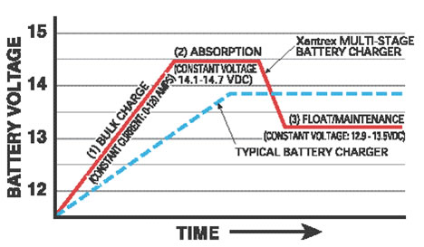
Built-In Battery Chargers: Most larger inverters can operate as battery chargers as well. This is easily and economically accomplished because of the design of most inverters. Inverters step up low voltage DC power and change it to 120VAC power. Battery chargers do the reverse of this. Transfer switches are also incorporated into these Inverter / Chargers so that the AC loads can be powered directly from the generator when the battery charger is operating. From a reliability, performance, and economical standpoint, built-in battery chargers are the way to go. Multi-Stage Battery Charging: A typical 12-volt lead-acid battery must be taken to approximately 14.2-14.6 VDC before it is fully charged. (For 24 volt systems double these figures for 48 volt, multiply by four.) If taken to a lesser voltage level, some of the sulfate deposits that form during discharge will remain on the battery's lead plates. Over time, these deposits will cause a 200 amp-hour battery to act more like a 100 amp-hour battery, and battery life will be shortened considerably. Once fully charged, batteries should be held at a lower float voltage to maintain their charge - typically 13.2 to 13.4 volts. Higher voltage levels will "gas" the battery and boil off electrolyte, requiring more frequent maintenance. Most automotive battery charger designs cannot deal with the conflicting voltage requirements of the initial "bulk charge" and subsequent "float" or maintenance stage. These designs can accommodate only one charge voltage, and therefore must use a compromise setting - typically 13.8 volts. The result is a slow incomplete charge, sulfate deposit build-up, excessive gassing and reduced battery life. The charger available in our inverters automatically cycles batteries through a proper three stage sequence (bulk, absorption and float) to assure a rapid and complete charge without excessive gassing. Factory battery charger settings on most inverter-charger combinations are optimal for a lead acid (liquid electrolyte) battery bank of 250-300 amp hours in a 70°F environment. If your installation varies from these conditions, you will obtain better performance from your batteries if you adjust the control settings.
There is no one correct voltage for all types of batteries. Incorrect voltages will limit battery performance and useful life. Check the battery manufacturer's recommendations. The Float Voltage setting should hold the batteries at a level high enough to maintain a full charge, but not so high as to cause excessive "gassing" which will "boil off" electrolyte. For a 12-volt liquid electrolyte battery at rest, a float voltage of 13.2-13.4 is normally appropriate; gel cells are typically maintained between 13.5 and 13.8. If the batteries are being used while in the float stage, slightly higher settings may be required. Charge voltage guidelines used here are based on ambient temperatures of 70°F. If your batteries are not in a 70°F environment, the guidelines are not valid. Temperature Compensation automatically adjusts the voltage settings to compensate for the differences between ambient temperature and the 70°F baseline. Temperature compensation is important for all battery types, but particularly gel cell, valve-regulated types which are more sensitive to temperature. Comparing Inverters: Inverters are compared by three factors:
|

|
Buynigeriaonline.com |
Service | Jobs | Contact us | About us | Faq |